Bar Code Scanner
Many different types of bar code scanning machines exist, but they all work on the same fundamental principles.
They all use the intensity of light reflected from a series of black and white stripes to tell a computer what code it is
seeing. White stripes reflect light very well, while black stripes reflect hardly any light at all. The bar code scanner shines
light sequentially across a bar code, simultaneously detecting and recording the pattern of reflected and non-reflected light.
The scanner then translates this pattern into an electrical signal that the computer can understand. All scanners must include
computer software to interpret the bar code once it's been entered. This simple principle has transformed the way we are able
to manipulate data and the way in which many businesses handle recordkeeping.
Bar code scanning emerged in the early 1970s as a way to improve the speed and accuracy of data entry into computers. Businesses
were just beginning to exploit computer tracking of stock and billing. The challenge was to find a quick, efficient, and relatively
fool-proof method of record entry for companies (for example warehouses or mail order companies) that maintain a small stock
of high volume items. The use of bar codes enabled clerks to keep track of every item they sold, shipped or packed without
a tedious and error-prone keyboard data entry process. Bar coding caught on quickly in clothing stores, manufacturing plants
(such as car makers), airline baggage checks, libraries, and, of course, supermarkets. The supermarket scanners which are
commonplace today are known as point-of-sale scanners, since the scanning is done when merchandise is purchased; point-of-sale
scanning is perhaps the most challenging bar code scanning application in use today. Supermarket scanners represent the most
advanced design of the various types of bar code scanners, because of the particular difficulties associated with reading
bar codes on oddly shaped items or items that may be dirty, wet, or fragile.
The first scanners required human action to do the scanning and used very simple light sources. The most common was the
wand, which is still popular because it is inexpensive and reliable. Wand scanners require placing the end of the scanner
against the code, because the light source they use is only narrow (focused) enough to distinguish between bars and stripes
right at the wand tip. If the labeled products are oddly shaped or dirty, this method is impractical if not impossible.
To make a scanner that works without touching the code requires a light source that will remain in a narrow, bright beam
over longer distances—the best source is a laser. Using a laser beam, the code can be held several inches or more from
the scanner, and the actual scanning action can then take place inside the scanner. Rotating, motor-driven mirror assemblies,
developed in the mid-1970s, allowed laser light to be swept over a surface so the user didn't need to move the scanner or
the code; this technology improved scanner reliability and code reading speed.
Later, holograms were chosen to replace mirrors, since they can act just like a mirror but are lightweight and can be motorized
more easily. A hologram is a photographic image that behaves like a three-dimensional object when struck by light of the correct
wavelength. A hologram is created by shining a laser beam split into two parts onto a glass or plastic plate coated with a
photographic emulsion. Whereas the previous generation of scanners worked by rotating a mirror assembly, holographic scanners
operate by spinning a disk with one or more holograms recorded on it.
Researchers at IBM and NEC simultaneously developed holographic point-of-sale scanners in 1980. Holographic scanning was
chosen not only because the hologram disks could be spun more easily than mirror assemblies, but also because a single disk
could reflect light in many different directions, by incorporating different hologram areas on the same disk. This helped
to solve the problem of bar code positioning; that is, codes no longer needed to directly face the scan window. Modern bar
code scanners will scan in many different directions and angles hundreds of times each second. If you look at the surface
of a scanner in the checkout lane, you will see lots of criss-crossed lines of light; this pattern was chosen as the most
reliable and least demanding on particular package orientation.
Raw Materials
A holographic bar code scanner consists of an assembly of preformed parts. The laser—a small glass tube filled with
gas and a small power supply to generate a laser beam—is usually a helium neon (HeNe) laser. In other words, the gas
tube is filled with helium and neon gases, which produce a red light. Red light is easiest to detect, and HeNe's are less
expensive than other kinds of lasers. They are much smaller versions of the types of lasers used in light shows or discotheques.
Lenses and mirrors in the optical assembly are made of highly polished glass or plastic, which is sometimes coated to make
it more or less reflective at the red wavelength of light being used. The light detection system is a photodiode—a semiconductor
part that conducts electrical current when light shines on it, and no current when no light is present; silicon or germanium
photodiodes are the two types of photodiodes most commonly used.
The housing consists of a sturdy case, usually made of stainless steel, and an optical window that can be glass
or a very resilient plastic. The window material must have good optical and mechanical properties; that is, it must remain
transparent but must also seal the scanner from the air, so no dirt or dust gets inside and blocks the light or the light
detector. Defects in the window can cause light to be transmitted at an unpredictable angle or not at all; both scenarios
affect the accuracy of the scanner.
The holographic disks are made of a substance called dichromated gelatin (DCG) sealed between two plastic disks.
DCG is a light-sensitive chemical used to record laser images, much like photographic film records light. It was developed
by Dow Chemical and Polaroid for their own holographic work, and it is sold in liquid form so that it can be coated onto a
variety of surfaces. DCG holograms are common in holographic jewelry (pendents, watch faces, etc.) and in the holographic
spinner disks sold in toy stores. DCG will lose a recorded image if it is left in the open air, which is why it must be sealed
between two layers of plastic.
The spinning motor drive that turns the disk is a small electric cylinder with a central spinning shaft, similar to the
kind available in an erector set. The shaft is attached to the center of the hologram disk, so that when the motor is turned
on, the disk spins.
Design
Bar code scanners require a team of designers to produce the completed assembly. First, a laser recording engineer designs
the hologram disk. There are a number of important features to be considered in this design. For instance, the disk must reflect
the majority of light that hits it (high efficiency), it must not distort the light so that the reflected beam remains narrow,
and it must reflect light in the chosen scan pattern while it is spinning. Also, the scan pattern must maximize the number
of readable orientations at which a bar code can be passed over the scan window and still be read.
The finished disk consists of many different holograms recorded in wedges on the same disk. Each wedge reflects light at
a different angle. As the disk spins, the light is scanned in a line. The orientation of the lines changes from wedge to wedge.
The hologram designer also specifies the exact power of laser to be used, a choice based on longevity, efficiency and safety
to the user.
After the hologram disk is designed, an optical engineer designs the placement of the laser and hologram disk, specifies
any lenses or mirrors required to steer the light in the right direction, and designs the detection system so that light reflected
from a bar code can be read efficiently and reliably. The designer must optimize the scanner's optical throw, defined
as the furthest distance an object can be held away from the scanner window and still be read correctly. It is the job of
the optical designer to consider how best to fit the components into the smallest space, with the smallest weight and expense,
while still placing the window at a convenient angle for normal use. For example, a supermarket scanner must have the window
facing up on the checkout stand, even though it may be more convenient to put the spinning disk sideways inside the box. Additional
mirrors can allow both of these constraints to be met.
An electrical engineer determines the best method of interpreting the electrical signals coming from the photodetector.
Electrically, the signals must be received and interpreted as a sequence of ON signals, (light reflected from a white bar),
and OFF signals, (no light reflected from a black bar). The resulting pattern is then converted by a computer into the product
information the pattern represents. A computer programmer may be employed to design the computer software that will translate
the code into product information, but the job of correctly interpreting the ON/OFF pattern is left to the electrical engineer.
The Manufacturing
Process
After all of the components have been designed, they are ready to be made and assembled. The hologram disk is generally
manufactured in-house, while the other components—lenses, mirrors, and laser—are usually purchased from other
manufacturers. The various parts are then assembled and tested.
Hologram disk
- 1 The first step in the manufacturing process is to mass produce the hologram disk. This disk is replicated from a master
hologram. All the disks, master and reproductions, are sandwiches made of plastic "bread" with DCG filling. Master disks are
made in sections, one wedge for each different reflection angle required in the final disk. A typical point-of-sale scanner
will have between 7 and 16 wedges on a single disk. Holographic recording is done with two laser beams that intersect at the
surface of the DCG sandwich, creating the holographic pattern. Adjusting the angle at which the two beams meet will change
the reflective properties of each hologram. Each wedge created in this way will act like a mirror that is turned in a different
direction.
- 2 Once all the required wedges have been recorded, they are assembled and glued down on a single transparent plate, which
can then be replicated. The glue used has optical properties that will not distort the hologram image, such as glycerin-based
adhesives will. There are many ways to replicate a hologram, but the most common for DCG holograms is optical replication.
The master disk is placed close to, but not touching, a blank DCG sandwich disk, and a single laser beam is used to illuminate
the master from behind. This transfers the pattern onto the blank.
Lenses, mirrors, laser
- 3 Other components—lenses, mirrors, laser, etc.—are usually purchased from an outside manufacturer. Lens,
mirror and scan window properties are specified during the design process. The manufacturer tests all of these components
as they arrive to confirm that they meet specification. Motors and lasers are tested for proper operation, and some are lifetime
tested to make sure that the bar code scanner will not fail within a reasonable period of time.
Housing
- 4 Housing can be purchased from a metal job shop, or it can be fabricated by the manufacturer. The size and exact shape
of the box is specified in design, and manufacturing converts those specifications into realizable sketches. The parts are
machined, assembled and tested for strength and durability.
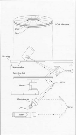
In a bar code scanner, a laser beam is directed toward an item with a black and white bar code symbol.
The light is reflected back and recorded on a spinning holographic disk. A photodetector then converts this light into an
electrical signal that can be read by a computer.
The spinning disk consists of a chemical substance, DCG, sandwiched between
two plastic disks. A typical holographic disk contains between 7 and 12 wedges, each of which reflects light at a different
angle. To make these disks, a disk master—comprising the various wedges glued onto a single transparent plate—is
first prepared. Next, a single laser beam illuminates the master from behind, transfering the pattern onto a blank DCG disk
placed next to (but not touching) the master.
Final assembly
- 5 Finally, the hologram disk is assembled with the spinning motor drive and tested. Scanning pattern, direction, and speed
are all examined. The spinning disk is then assembled with the optical system (the laser and mirrors). Placement of the laser
often depends on space considerations: the laser can be aimed directly at the spinning disk, or at a mirror that guides the
beam to the disk, if this makes the package smaller.
- 6 The disk and optical system are tested as a unit. When the assembly passes inspection, it is mounted permanently inside
the housing and sealed with the scanning window.
Quality Control
There are several stages to quality control in bar code scanner manufacturing. To begin with, there are several test criteria
that are defined within the bar code industry and that must be specified by all manufacturers. These include:
- First Pass Read Rate (FPRR)—the percentage of time that a code can be read the first time it passes the scan window
- Rejection Rate—the number of scans per million which simply won't be read
- Read Velocity—the range of speeds with which a code may be passed over the surface of a scanner
These properties will relate to the optical, electrical and mechanical properties of the scanner. Mechanically, scanners
are run for several days (and some select units will be pulled from production for longer lifetime tests—up to several
years) to insure that the motor will continue to turn the disk consistently at the expected speed. Since the ability to differentiate
between wide and narrow bars in a code is related to the speed at which the disk turns, it is critical that the motorized
disk continue to operate in a predictable way. Spinning speed will also relate to Read Velocity, and may need to be adjusted
to match the average speed that a clerk will use to drag items through a supermarket checkout. Mechanical failures may indicate
a mismounted or imbalanced disk or other mechanical problems that need to be corrected.
Optically, scanners are tested for code reading consistency. For a good bar code scanner, this number should be greater
than 85 percent. Commonly, 75 percent to 85 percent is achieved. If the scanner cannot meet this criteria, it is sent back
for an inspection of the optical system—cleanliness of components and proper functioning of the laser and detection
system.
Electrically, scanners are tested for the Rejection Rate. Holographic scanners scan the light over a bar code 100-200 times
per second. This allows the computer to compare many different readings of the code for accuracy. But if there is some problem
with the electronics, the computer will begin to "reject" scans, or simply refuse to read them. Part of this test uses bar
codes that are imperfect in some way—codes containing ink spots, bars of non-uniform width, etc. The manufacturer has
to produce a scanner that can tolerate some glitches in the code printing process. This is another reason to use a multiple
scan and cross-check technique.
The Future
The future of bar code scanning technology will take a number of diverging pathways. More general use of bar code scanning
requires cheaper and smaller light sources that will improve simple instruments like the wand scanner. Semiconductor lasers,
for instance, may make the wand a more attractive instrument to users. In addition, some children's learning tools and toys
are starting to appear with interactive bar codes rather than push buttons. In this way, new modules can be added to the same
bar code scanning toy. There are some home-shopping systems that are beginning to exploit this technology, allowing people
to do grocery or clothes shopping at home by scanning selections from a catalog using their telephone and a modem.
Laser scanners, on the other hand, are beginning to find more and more complex applications as the technology becomes more
reliable and easier to use. More industries are using bar coding to track complicated lots of custom-manufactured items, record
steps in a manufacturing process, and monitor activities in their plants. Other optical assemblies may be developed that will
allow this technology to become even more flexible in size and utility.